Loading...

Eric Petersen

Overview

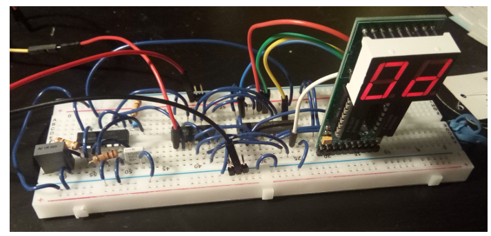
I made a circuit to control motor RPM through negative feedback while periodically updating a 7-segment display with the current speed. This was a strong introduction to both analog and digital electronics. I learned to use components such as op amps and latches, and precisely diagnose and debug electrical issues.

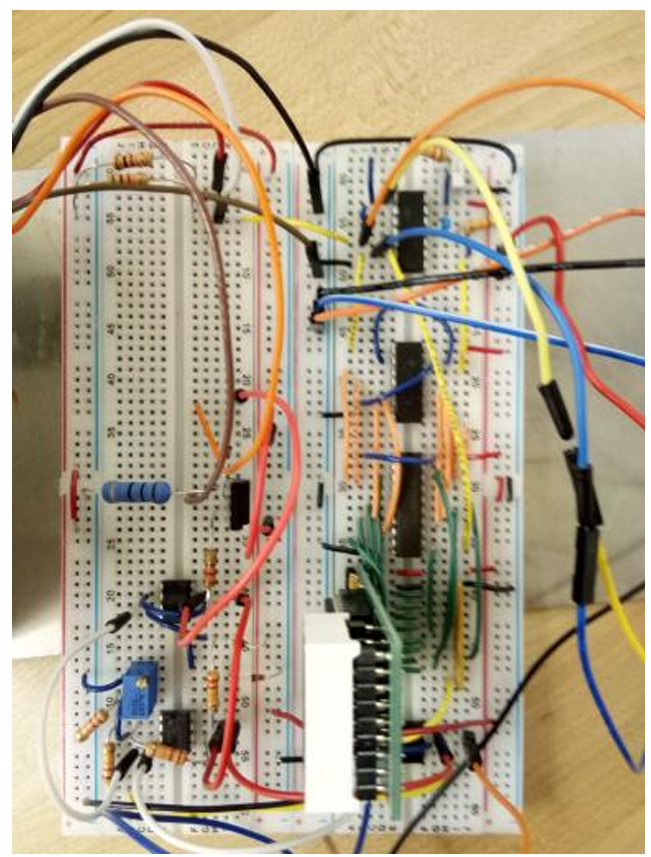
full breadboard circuit
Completed circuit on a breadboard.
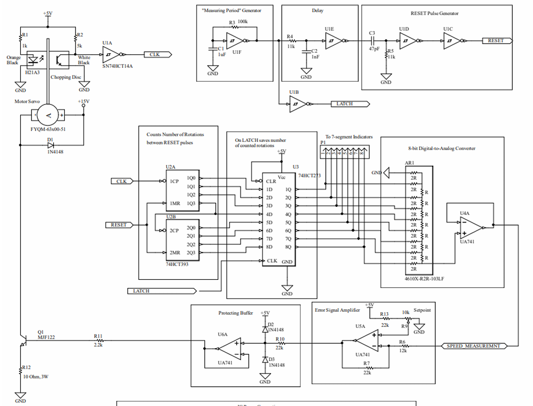
full circuit schematic
Schematic of final circuit.
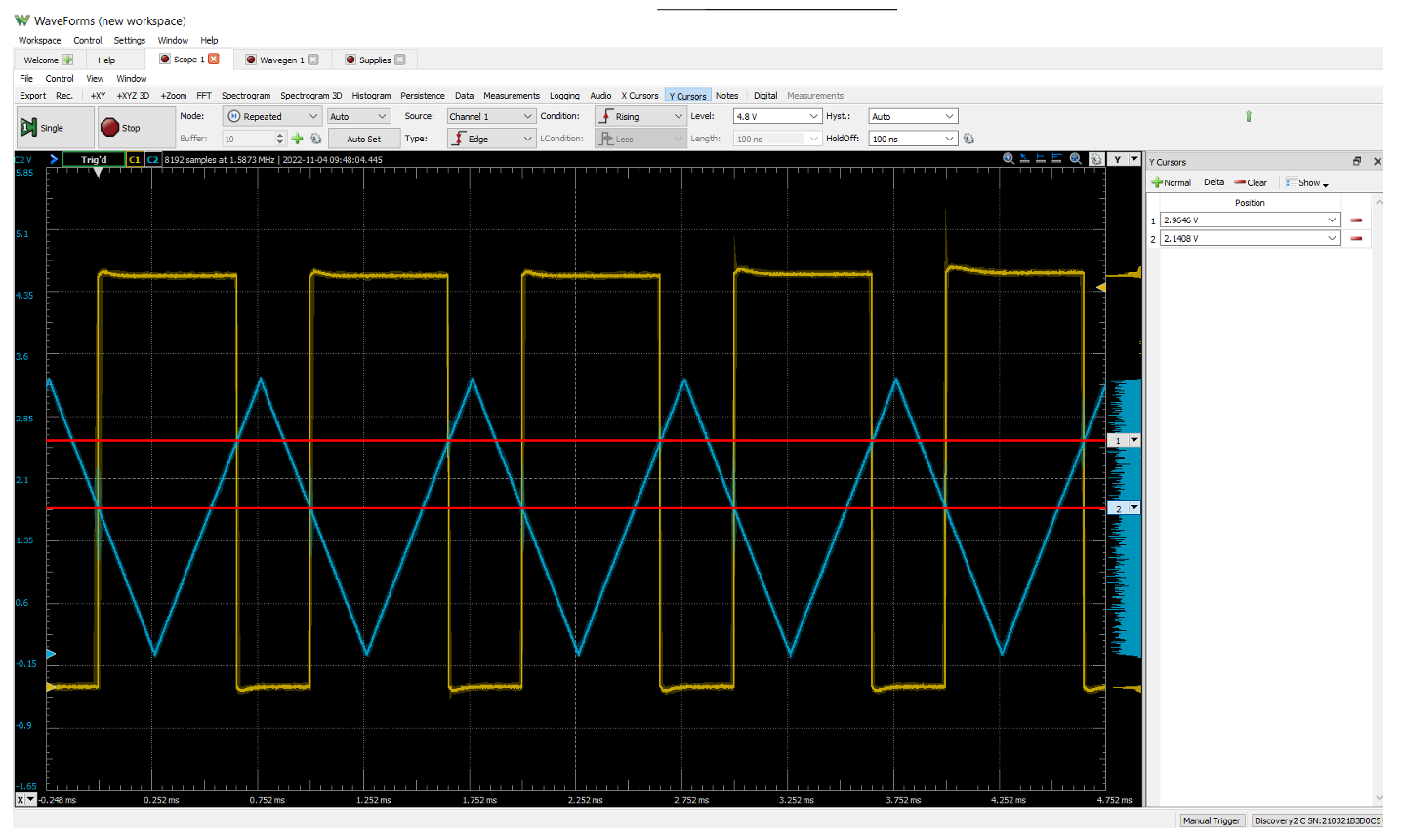
scope schmitt trigger
Picture of scope channels on Schmitt trigger.
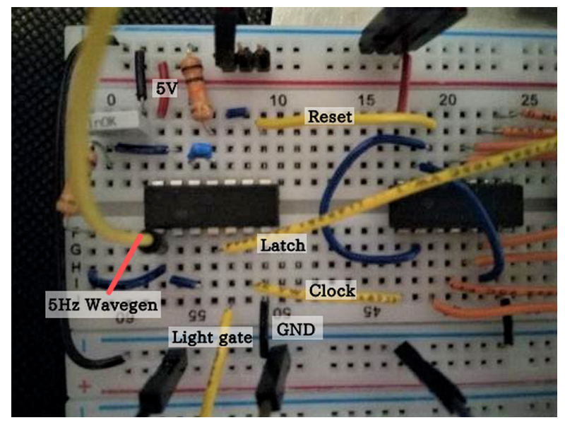
input to latch labelled
Labelled section of circuit, for debugging.
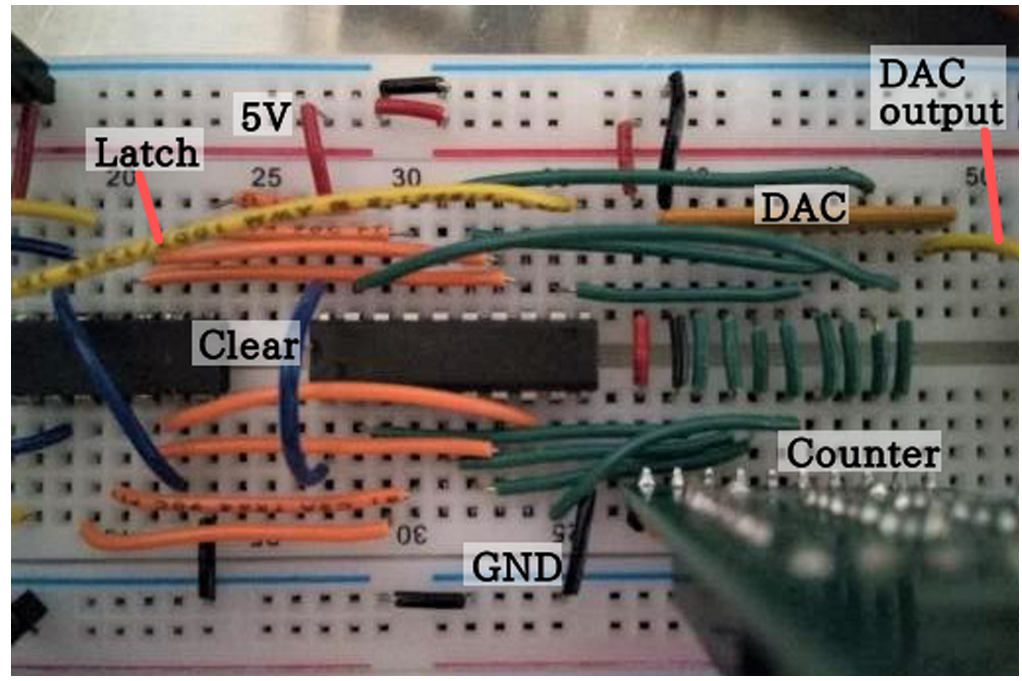
latch to DAC labelled
Labelled section of circuit, for debugging.
partially built circuit
Circuit in progress. Lack of colour coding and loopy wiring proved a nuisance...